
With the rods cut to length, the next step is to construct the frame for the Prusa Mendel RepRap, and this is a bit of fun. The machine takes shape, finally.

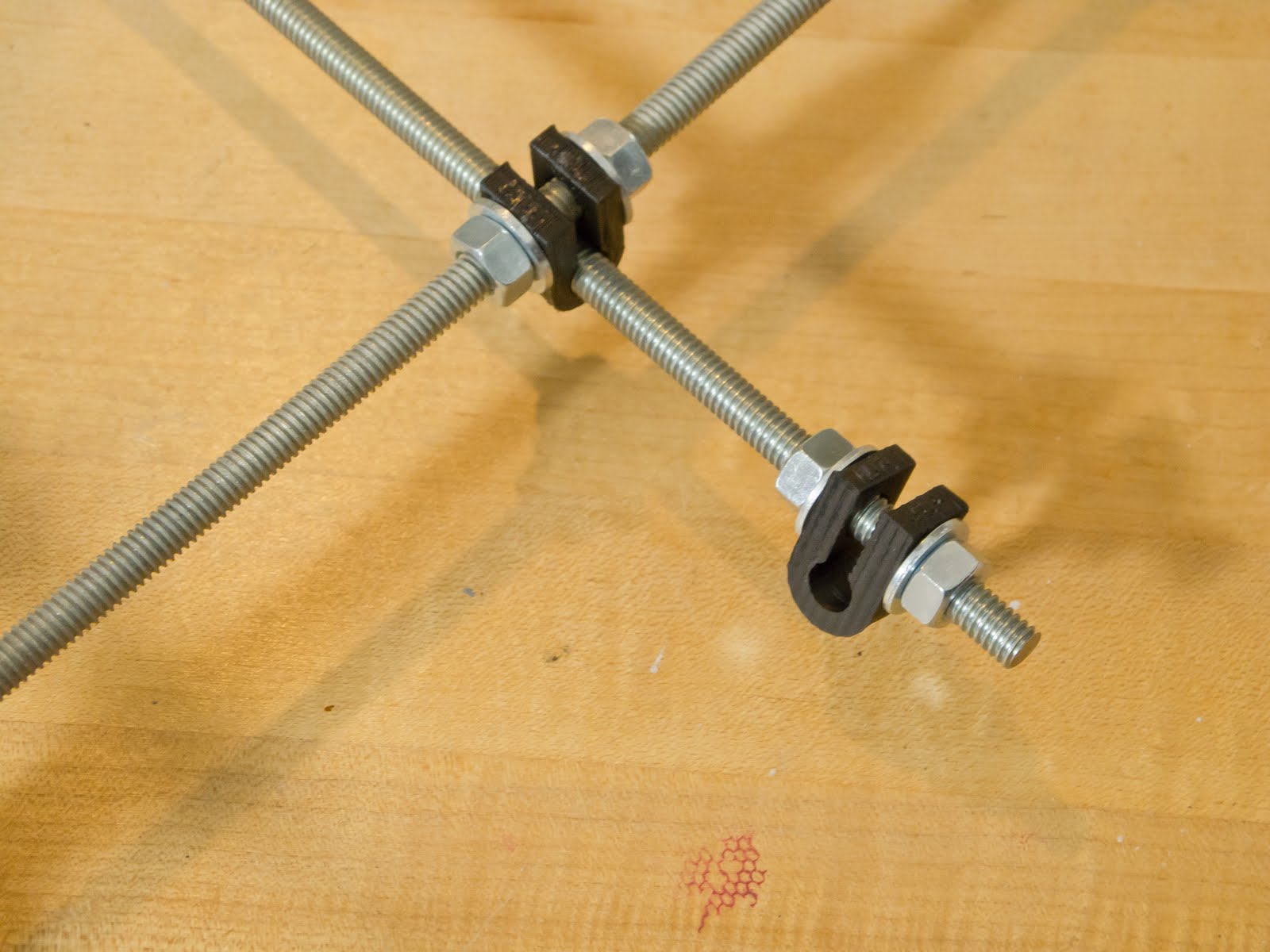
Before you get started we should make sure your printed plastic parts are cleaned up and ready to use. Like these bar clamps pictured above, they might need some work. Take a craft knife to clean up the stringy bits around the outside, and push drill bits of appropriate size through the holes by hand. Run the bit back and forth, twisting a little between stokes, to make sure you have the hole smooth all the way around. Cut apart any of the pieces that came stuck together due to being printed close together.
Triangles
The triangles of threaded rod make up the main structure for the frame.
The parts you'll need are three 370mm rods (14 5/8"), 14 washers, 14 nuts, bar clamp, three vertices (two footed and one top vertex) a 5/16" drill bit and hobby knife. You'll also need a ruler.

1.) Begin building by threading a bar clamp assembly on to the middle of a 370mm rod. A bar clamp assembly consists of a nut, washer, bar clamp, washer and nut, in that order. Do not tighten the nuts around the bar clamp. They should remain loose until we install the Y axis, later.

2.) Put a footed vertex assembly on both ends. This will form the base of the triangle for the frame. The vertices are positioned with the foot down, inserting the rod into the lower holes, in the narrow side. The vertex should face outward, curving away from the center of the rod. The vertex assembly is a nut, washer, footed vertex, washer, and nut, in that order. The outer-most nut should just fit on to the rod. Keep the assembly loose for now.

3.) Loosely assemble two more pieces of 370mm rod in the remaining holes on the narrow of the vertices. Be sure to follow the pattern of nut, washer, plastic, washer and nut. Throughout the construction, wherever there is a nut holding a plastic piece in pace, there is always a washer in between. Again, the outter-most nut should just barely fit on to the end of the rod, and nothing should be tightened down yet.

4.) At this point you should have a triangle shape missing the vertex at the top. Thread on a nut to the ends of each open rod, slide on washers then carefully insert the rods though the non-footed vertex, positioned so that the vertex forms a U shape. As always, if you have to use force to get something to fit you are doing something wrong and you need to stop and figure out what it is. The nuts and washers should start about an inch from the end, and then after you put on the vertex you can thread on the nuts further down until the rod just starts to peak out of the plastic. Do this on both sides and fit washers on to the rods. Threading both inside nuts a little further, you should be able to start both of the outer nuts. With both nuts started you can proceed to turn all the nuts until you have them all fully on to the rods at the end. Following this process is easier than threading them on individually, because things get kind of tight up there when you don't do them together.

4.) Hand tighten all the nuts on the vertices and you wind up with a sturdy structure. As you go around the triangle and tighten the nuts, measure the distance between the vertices. The vertices should be 290mm (11 13/32") apart, measuring from the inside edge of the plastic. Be sure the ruler does not ride up on the washer next to the printed piece. Try to make sure there is about the same amount of threaded rod coming out of the nut on each end of each rod as you adjust, measure and tighten.

5.) Repeat all these steps to build the second triangle.
Front Cross Supports
Next, assemble the front cross supports for the machine. This construction will link the two triangles together with two of the 294mm sections of threaded rod.
The parts needed for this step are two 294mm (11 5/8"), 17 nuts, 20 washers, two fender washers, two bar clamps, and the Y motor bracket printed part.
1.) Make the bottom front cross support by threading on the Y bracket assembly at it's lower junction on to a 294mm rod. The Y bracket has two 5/16" holes in it. There are two semi-circular sides, one with a larger radius than the other, and a side that is straight. The bottom junction is the 5/16" hole that is at the end of the straight section. The Y bracket will be oriented so that the straight section is parallel to the table, and the larger diameter semicircle faces inwards toward the machine. Thread on a nut, a washer, the Y bracket, then a washer and nut.
UPDATE: Proviso, caution, addendum alert! Measure the motor shaft length, or refer to the motor specifications (specs for the ones I got from Ultimachine, here.) If it's 25mm long, you're all good. If, like mine, the shaft is 20mm, leave out the two spacer washers between the nut to the right of the Y motor bracket and the left fender of the pulley. Details pending.

2.) The top front cross support looks complicated, but if you break it down it's really not so bad. Like the bottom cross support, the Y bracket on top has a nut with a washer against the plastic on either side. Right up against the Y bracket's right nut there is a pulley assembly (you kids in the back, stop giggling. Thank you.) Since there is already a nut for the Y bracket, you just need to put two washers on as as spacers. Then slide on a fender, a washer, a bearing, a washer, and a fender, held together with a nut. On either side of the Y bracket and pulley there is a bar clamp assembly that's just like the ones that went on the bottom of the triangle. The ends of the rods are finished with nut, washer, washer and nut combos.

Rear Cross Supports
Since the rear cross supports are not joined by a bracket as is the front, you just need to prepare them for final assembly of the frame.
The parts you need for this step are two 294mm rods (11 5/8"), 14 washers, 14 nuts, two fender washers, a bearing, and two bar clamps.
1.) The top cross rear support rod has a pulley assembly in the middle, but with a nut instead of the spacer washers. On either side of the the pulley add a bar clamp assembly. Finish the ends of the rod with a nut, washer, washer, nut combo.

2.) The bottom rear cross support rod is simply a nut, washer, washer, nut combo on each end.

The top cross supports are built in the process of constructing the frame.
The parts required for this step are two 440mm (17 5/16") rods, 12 nuts, 16 washers, and the previously assembled and prepared frame parts.
1.) Remove a nut and one washer each from one end of the front cross supports. Insert the ends of the rods through the holes of one vertex of a triangle. The top cross support should be oriented with the frame up so it is closer to the top vertex than the bottom cross support. Fasten the rods to the triangle with the washers and nuts. Leave loose.

2.) Repeat for the other end of the front cross supports. Do not tighten.
3.) Assemble the rear of the frame by positioning the top and bottom rear cross supports in the remaining footed vertices, using the washer and nut on the ends of each rod to attach them.

4.) Set the frame on it's feet and begin building the top of the frame by inserting a 440mm long threaded rod though one side of the top vertex of a triangle. Before inserting it into the opposite vertex, thread on a washer, two nuts and a washer, in that order. Now insert the threaded rod though the vertex opposite the first. Turn the nuts so that each holds a washer against the inside of the opposing top vertices about 234mm (9 7/32") apart, and so that even amounts of threaded rod protrude from the outside of each vertex. Fasten the rods loosely in place with washers and nuts.

5.) Repeat for a second top cross support rod.

Tighten the Frame
At this point the frame should be a little loose, but roughly in the correct shape.

1.) Make two jigs for precise measurement between vertices. The jigs may be made from any firm material. Wood dowels would probably be best, but I just used what I had on hand. I was afraid that the potential for and uneven end would introduce some variability so I cut away part of the ends with a skill saw.

2.) Make one jig to precisely 290mm (11 13/32") and label it "J1". It's really important to get the jigs to the exact length specified. My technique was to cut it a few millimeters too long and gradually file it down to length, frequently checking against a ruler.
3.) Make one jig to precisely 234mm (9 7/32") and label it "J2". Use either metric or SAE units, as they are approximately equivalent but not interchangeable.
4.) Use J1 to carefully adjust the distance between vertices of the triangles. Measure from the inside of the vertices. Tighten so that the nuts won't move, but be careful not to crack or crush the plastic.

5.) Use J2 to carefully adjust the distance along the cross supports between triangles. Measure from the inside of the plastic pieces. Tighten the nuts with a wrench but do not crush the plastic.
Bottom Cross Support
At this point the frame should be stable and precisely adjusted to size.
For this step the following parts are required: one 440mm (17 5/16") rod, two bar clamps, four nuts, and four washers.
1.) Insert the 440mm rod through the bar clamps under the frame. Note: the visual instructions I used indicate this rod should go on to the bar clamps above the bottom support rods. However, some people reported that this caused wear on the belt driving the print surface. Now it is recommended that this cross support be slung under the machine. I followed the new recommendation. Whether that will come back to bite me remains to be determined.
2.) On to each end of the bottom cross support rod assemble a bar clamp. The bar clamps should be finger tight and jut out from the rod in the same direction.
3.) Align the bottom rod. Construct a plumb line. I used yarn and a pair of nuts I'd used earlier when cutting the threaded rod. Suspend the plumb line from the notch a top motor mount with the weight just off the table enough for it to swing freely. The cross support will be aligned slightly off-center. The vertical holes formed by the bar clamp should align with the plumb line.

The frame is complete!
There is video of this entire process. I will update this post as finished video becomes available.
No comments:
Post a Comment