Showing posts with label reprap. Show all posts

Tuesday, April 03, 2012

RepRap SitRep


The Hains is due for a rebuild, adding longer leadscrews and the MakerGear Z-axis stabilizer clamp (a.k.a., lower-z-bar-clamp, right and left), and replacing the fender washer pulleys with printed ones. Before I dare tear down the Hains I have to first get the Desmonda working. For the Desmonda the rods are all cut, parts are all gathered, the heat core just needs it's final cook to be ready for assembly into the hot end, and construction of the frame has begun. I still think that if it weren't for the fact that I'm trying to figure out the exact length the rods need to be to use acorn nuts on the ends I could get it done in a day.

By the way, so far I've figured out that the triangle frame pieces for a Prusa should be exactly 370mm long, the x/z axis crossbars at the top need to be exactly 440mm long, and the x-axis crossbars (4) need to be exactly 282mm long. Still working on the lower z-axis bar, lead screws and drill rod. I'll be posting an updated instruction set for cutting the bars when I get them all sorted.

- Posted using BlogPress from my iPad

Location:Glenwood Dr,Kalamazoo Township,United States

Thursday, December 08, 2011

Printing Colbert is Hard


This is supposed to be the bust of Stephen Colbert, but it kind of reminds me of that scene from Total Recall. Travesty, both the movie and the print.

I've been troubled by this issue from the start. All my big prints have failed in similar fashion, most regrettably the Makerbot plates for Mendel parts. Small prints are no trouble. It seems happen most during the travel phase of the print, as it moves any long distance without extrusion. I've tried a lot of things, including slowing the entire print, travel and all, down to a crawl.

The famous Art of Failure article describes this problem as an issue with insufficient current. I've been playing with the current on the motors a lot. I turn them up until they stutter from too much juice, and I can't seem to make any headway.

I have to solve this, though, because students are going to want to print some largish things.

Thursday, November 17, 2011

3D Printing Web Site - Open3DP


Al pointed me to an interesting web site today, Open3DP. I think I may have seen it before, but it's worth taking note of here so I'm glad to revisit it. The top article today is about a new book from the same people who wrote the Build Your Own CNC Machine.

Tuesday, November 01, 2011

What 3D Printers Are Good For


A lot of times I'm asked what 3D printers are good for, as in, why would someone want a 3D printer besides the cool factor. Xnaron on YouTube posted a project update for an antenna tracker, his own creation, and all the structural components for the machine are printed on his RepRap. There's a lot of innovation going on here, and 3D printers enable makers to make more complex and intricate designs than they might otherwise be able to fabricate.

Monday, October 31, 2011

Course Description for Summer 2011 Class

The plan is for me to teach a 3D modeling class at KIA in the summer, an 8 week semester. The course descriptions are due today. Here's mine.
3D Modeling with Blender
Prerequisite: None 
Design 3D objects in Blender, a free program used to create everything from sculptures to feature-length animated films. This introduction to Blender is aimed at creating sculptures, particularly for designs to be printed on a 3D printer. Basic modeling features of the program will be covered, and students will have the opportunity to print out their digital creations on a RepRap 3D printer to keep. Each student will be able to print one object, scaled to fit within a 150mm x 150mm x 100mm print envelope, with a maximum resolution of 0.5mm. 
Materials: I need to buy $50-$90 worth of plastic filament and $30 worth of blue tape. 

Saturday, October 29, 2011

The 3D Printer Class I Want to Teach


My department head at KIA found this class in New York that's like what explained to him as one of the classes I want to teach. The only difference is that I'll be doing it with a RepRap instead of a Makerbot. After reading this page, though, it's hard to write a class description that doesn't sound like a complete ripoff, but I swear I thought of it first!

Here's what I have so far:
 3D Printing
Prerequisite: None 
Turn a digital design into a real, three-dimensional object at the click of a button. Experience 3D printing, a cutting edge technology that turns electronic files into physical shapes you can wear, use or display. Artists, innovators and makers of all kinds will enjoy learning about this modern marvel, but it will be of particular interest to sculptors, jewlers, and modelers. Students will download a 3D model file from the Internet, prepare it for printing, and get hands-on experience with a RepRap 3D printer to make the object to keep. Students will get a preview of software they can use to design their own 3D models suitable for printing. A single print can take hours, so students will schedule time with the instructor to print their model outside of the regular class schedule, and must be available to monitor the print for its duration. Students with previous experience in 3D modeling are welcome to bring their own design for printing. Only prints of up to 150mm x 150mm x 100mm can be accommodated. Students who complete this course may be given access to the printer for the duration of enrollment at the KIA.
Materials: I have to buy $50 - $90 worth of plastic filament and about $30 worth of blue tape. 
I think I have too many "students" in there, maybe.

Stuart and I have talked about making this a three week course, taught twice during the Spring semester, and then I will teach an 8 week class on Blender in the summer. Class descriptions are due Monday, so comments are welcome if you hurry.

Sunday, October 23, 2011

How to Build a MakerGear Hot End: a Video Guide in HD


A complete series for building a MakerGear hot end, from unboxing to finished piece, in excruciating detail. Over an hour and a half of step-by-step demonstration, filmed as I worked, learned and discovered.

STEP 1: WRAPPING THE HEAT CORE


STEP 2: FIRST CERAMIC APPLICATION


STEP 3: RETOUCHING THE CERAMIC


STEP 4: FIRST CORE COOK


STEP 5: WIRING THE HEAT CORE


STEP 6: FINAL CERAMIC APPLICATION


STEP 7: FINAL CORE COOK


STEP 8: THERMISTOR ASSEMBLY


STEP 9: FINAL ASSEMBLY

Saturday, October 22, 2011

UStream of Prints


Video streaming by Ustream


Don't forget my UStream channel where I'm doing live broadcasts of RepRap prints on a semi-regular basis, and when it's not live, watch past updates recorded live. I announce live streams on Twitter [@kwixson] and on Facebook. So follow me and check in on the prints to see what's cookin'.

Tuesday, October 18, 2011

Prusa Mendel Reprap: Calibration Step Four


Test cubes. So many test cubes.

Now that you've had your glorious moment with the first print on your printer, it's time to get down to the business of making your prints spectacular. That process begins with a download from Thingiverse. Spacexula's calibration objects are the standby of all RepRappers getting their machines tuned and settings set. The page for the calibration set is quite informative, but really the big deal is printing the 20mm x 20mm x 10mm cube. You'll see a lot of this object coming off the printer.

So, download the set and print the first one of many cubes. When it's printed one of the first things to check are the dimensions. You calibrated the steps_per_unit in firmware earlier, but now is the real first practical test. Get some calipers and measure the width, depth, and height. Go back to prusajr's calculator and make adjustments to the firmware settings. Remember that the line width will throw off the measurement with the calipers by one full line width. So, whether you print 20mm wide or 100mm, an accurate print will measure one line width too wide. Subtract that width from your measurement for the calculator. If you have a .35 nozzle that value is somewhere in the neighborhood of .54mm.

Print the cube repeatedly, measuring and adjusting the x, y and z firmware settings until you home in on the precision you expect. Don't overdo it, though--it can only be just so precise.

Calibration Step Four: Understanding Skeinforge

The good news is that there are only a few really important settings. The even better news in my opinion is that with Skeinforge there are lots of things you can customize and fine tune. There is a program based on Skeinforge called SFact which claims to be simple to use and simple to calibrate. It's not to my taste. Skeinfoge can be a little intimidating at first, but you can get the hang of it quickly if you try. Take it from one beginner to another.

The essence of the following settings has to do with calibrating the machine's flow rate. How much and how fast should the plastic flow out of the nozzle. How fast should the machine move relative to the flow of plastic out of the nozzle? Getting these answers right is the difference between good prints and bad.

A Few Important Settings

Line height and width over thickness ratio (on the Carve tab), filament width and packing density (on the Dimension tab), infill ratio and shells (on the Fill tab), and the feed rate and flow rate (on the Speed tab). With the starter profile you got in Calibration Step Two, you should have some decent defaults and the test cubes shouldn't be too much of a mess.

Dimension

The first stop for Skeinforge is the dimension tab, and there your destination is the filament diameter field. It's important to measure the filament you are using at several places along a 100mm length, and in several angles. Rotate the calipers around the filament. Take down all the measurements and average them. The packing density should be 1 for PLA, and .85 for ABS. Packing density accounts for the stretching that occurs when the filament passes through the pinched wheel extruder. ABS is softer than PLA and stretches more, so it is a bit less "densely packed"than PLA.

Carve

Carve is a very important tab. Line height and width over thickness (often said as w/t) work hand in hand and can greatly affect the quality of the prints. In the calibration set from Spacexula there is a thin wall model whose purpose is to fine tune these two settings. The line height is supposed to be around 80% of the diameter of the nozzle. For a .25mm nozzle, for instance, the ideal line height setting is .2, which is exactly what I'm using to print at after a lot of experimentation. Width over thickness is the setting that tells the machine how much wider the line should be relative to it's height. A perfectly round extrusion profile wouldn't put much of the surface area in contact with the lines above or below, so a somewhat flat extrusion profile is better. Typically a good setting is somewhere between 1.5 and 1.9.

Speed

One issue you might notice while printing test cubes is that maybe the filament gets jammed, or sometimes the extrusion kind of delaminates (doesn't stick down) and bunches up around the nozzle while doing solid layers, or you have trouble walking that fine line between motors skipping steps and having the power turned up so high your motors fry. These can all be symptoms of too high a speed. You will want to print as fast as you can get away with, but which doesn't cause these or other problems. Really the speed you can achieve depends on your motors. With my motors (and nozzle -- they're related) I haven't been able to print reliably higher than 40mm/s. The feed rate and flow rate must be the same number. They are different fields, from what I understand, because Skeinforge used to calculate flow rates differently. I could be wrong, but that's what the best expert on the IRC channel is saying, and I've been able to get good, quality prints by sticking to his advice.

Later, when you get some experience printing, you'll want to come back to the speed tab to work with the settings for bridging prusa parts, be sure to try the quick bridging calibration piece on Thingiverse.

Fill

Lastly, there's fill. Of course, the fill settings determine how the interior of the model is supported. The infill solidity ratio is the key setting, and can be anything from 100% (1.0) to 0% (hallow). PrusaJr says he prints RepRap machine parts with a 20% (0.2) fill. I feel more comfortable printing them at 30% or 35%. For small parts, especially gears, I often use 100% fill.

Also, you can choose what kind of fill pattern you want in Skeinforge, a notable feature not available in SFact. I heard an engineer on the IRC channel say that with the hex fill pattern you can achieve 30% greater strength with the same amount of fill as line fill patterns. I like to use hex, personally, and I don't find it takes very much longer than line fill patterns to print. Besides, it looks cool!

Once you get all of the previously mentioned settings dialed in, you might want to come back to the fill tab and take a look at the oft unappreciated grid extra overlap setting. Changing this value will adjust the distance between parallel lines of solid layer fills. If you notice that the top layer of your print has gaps between the lines, you'll want to increase this a bit.

Done

That's Skeinforge in essence. From here you can do like I did and go to the Skeinforge manual and go through each setting one by one. A lot of the things you just won't tough. Regardless, when you get done with Skeinforge there's one last thing you can do to get your machine set up for happy printing.

Next up: Calibration part five: Bookends

Tuesday, October 11, 2011

Prusa Mendel RepRap: Calibration Part Three


In Calibration Part Two I offered an entrée into RepRap firmware, and I know you're probably excited to start printing. Good news, that's what happens next. The thing that's needed now is the program that slices the model into layers and writes the program for movements of the extruder head. The program for that is called Skeinforge.

Skeinforge can be used as a stand-alone program, but also as a plug-in for pronterface.py. With it, you can load a file that has not already been sliced and diced into gcode, the step-by-step instructions sent to the printer. Normally you load the gcode file directly into the printer host, which in this case is pronterface.py.

If you haven't already, download Skeinforge and extract the folder into the printrun folder. The thing you need to do to get Skeinforge working as a plug-in for pronterface.py is simply ensure that there is a folder called skeinforge containing all the Skeinforge files in the same folder as pronterface.py.

You can open the stand-alone application by navigating to printrun/skeinforge/skeinforge_application and running the file skeinforge.py. Like pronterface.py, Skeinforge is a Python script, so you may need to take steps to permit the program to run, and of course you will need to have Python and associated dependencies installed and operational. Run the program once and a hidden folder will be created in your home folder called .skeinforge (as in, dot skeinforge). This is where the printer profiles are kept.

To get printing quickly, you can download and install a profile that Spencer Renosis maintains as a service to beginners. He's quite proficient at creating profiles that provide a great starting place for printers. He has instructions for how to use the download, but essentially the process is to replace the .skeinfoge folder on your computer with the one he provides. A word of caution, as of this writing his profiles are a little behind the current release of Skeinforge. Profiles for different versions of Skeinforge are incompatible. If it looks like his profiles have not been updated to the most recent version of Skeinforge, the package of files usually contains the version of sprinter and Skeinforge he is currently using on his printers. You can change over to those for the time being.

Open Skeinforge again and select the most recent stable profile for Extrusion,  which has the date of the profile and the version of Skeinforge used to create it in the name. The README file has specific information about the name of the profile. Close Skeinforge.

Now it's time to print! Open pronterface and load a file. I wanted to start with something fun, so I downloaded the Movember Ring from Thingiverse.com. On that page of Thingiverse you can see two files at the bottom of the page ready for download. One is the SCAD file and the other is the STL. SCAD is a file format of OpenSCAD, a 3D modeling program and the top of the 3D printing toolchain: 3d modeling program (OpenSCAD) > stl > gcode (skeinforge) > printhost (pronterface) > firmware (sprinter) > printer.

The STL file is the intermediate format of a 3D model, and it's ready for slicing in Skeinforge. The STL file doesn't represent any particular software, it's just a kind of model format. STL is to 3D modeling what a JPEG is to Photoshop.

Download that STL file and select it as the file you load into pronterface.py. You will see messages in the pronterface monitor pane showing the progress of Skeinforge as it prepares the file for printing. When it's done, a small image of the base layer of the object will appear in the layer preview pane.

Warm up your nozzle to the appropriate temperature and hit the print button. Obviously, connect to the electronics first. Your printer should start going through the motions. Watch with amazement as the extruder moves to home and then moves around the print bed. It's awesome to see the printer exhibiting printer-like behavior the first time!

Keep close and be ready to hit the on/off switch on the power supply at any moment that something seems not right. It's possible that you will need to restart the first print several times to make adjustments. Usually the nozzle is not the right height over the print bed the first time and some tweaking is necessary.

Don't expect too much from the first print. Work any problems and try to get a good print by ensuring the bed is level, the nozzle is the right height, and the temperature is where it should be. But if the first print looks a little messy, that's still okay. You're finally printing and that's very cool.

Next Up: calibration step four, Getting to Know Skeinforge

Friday, September 30, 2011

Prusa Mendel RepRap: Calibration Step Two


In Calibration Part One I tackled physical calibration. Part two of the calibration process is in the firmware settings. I used sprinter firmware to start with, but have recently switched to marlin. Marlin is almost identical to sprinter in configuration, so this information will work for both. If you have a different firmware, the idea is basically the same. I'm also assuming you will be using RAMPS 1.x, the Arduino IDE and pronterface.py in this tutorial. If you are using RAMPS, and you want the marlin firmware, be sure to use the link above to get the "non-Gen6" version. I won't be going into the particulars of each program I name in this tutorial. Look for upcoming posts for an examination of each piece of software.

Step Two: Firmware and Temperature Ballparking

Fortunately, this is rather straightforward. What you will be aiming for is that when the bot is instructed to move +1mm on the axis, or to extrude 1mm of filament, it actually does that to within 0.02mm. That is about the maximum positional accuracy of your typical Prusa Mendel RepRap.
  1. Open the Arduino IDE
  2. Open the firmware .pde file (i.e. sprinter.pde)
  3. Switch to the configuration.h tab
  4. Scroll down to find the line:
    float axis_steps_per_unit[] = {80, 80, 3200/1.25,700}; 
  5. Open pronterface.py and connect to the electronics
  6. Power up the power supply and make sure each motor moves in the correct direction with small moves. If it doesn't move in the right direction, STOP. You either need to change how you have your motors plugged in or you need to change the direction the motors move in the firmware (in configuration.h).
  7. Home the X axis and press the X +100 button in pronterface
  8. Did it move 100mm? Measure it to find out. The X axis is easy to measure when the nozzle is close to the print surface. Make a mark on the blue tape under the nozzle at home, and then where it lands after X +100, and measure the distance.
  9. Use the RepRap Calculator to figure out the new steps_per_unit value for the X axis.
  10. Enter 100 in the desired movement field
  11. Enter your measurement of actual movement in the next field
  12. Copy and paste the steps_per_unit value from configuration.h for that axis in the third field of the calculator. The steps_per_unit values are in the order X, Y, Z, E and each value can be an equation instead of a numerical value. So the default value for Z is 3200/1.25, meaning 3,200 divided by 1.25. You can substitute the actual value for the Z parameter.
  13. Copy and paste the new calculated value (up to three decimals) back into configuration.h and save the file
  14. Exit out of pronterface.py
  15. Press the reset button on the electronics
  16. Upload the firmware to the electronics
  17. Rinse, repeat until that axis is as finely tuned as your margin of error for measuring will allow. Additional refinements to these values can be done after the machine starts printing.
  18. Rinse and repeat for the Y and Z axis.
Ballpark the temperature.
  1. The thermistor attached to a hot end is not calibrated. So while 185 deg. C might be the right temperature for PLA, it's not as easy as setting the temperature to 185 in pronterface.py and forgetting about it. You'll need to find the melting point of the plastic you're using and then start printing with a temperature that is a reasonable setting somewhat higher than that minimum.
  2. Heat the nozzle up to a good starting temperature. For PLA you might want to start at 185 deg.
    Caution! If this is the first time you have turned on the hot end, monitor the temperature carefully and if it soars way past the target temperature (by more than 10 degrees) or doesn't register much of a change in temperature, turn the power supply off immediately. Don't freak out if the hot end starts to smoke, though. The first time or two of heating the nozzle, it will smoke.
  3. Set the speed on the extruder (in pronterface.py) to about 150 and extrude 30-50mm of filament.
  4. Immediately turn the nozzle off (set the temperature to 0) and keep the nozzle clear by removing the ooze and wiping the nozzle tip with paper towel.
  5. When the temperature has reached room temperature again, turn it back on to 185 deg. and turn on print monitoring
  6. Watch the tip of the nozzle carefully. Note at what temperature the plastic starts to ooze out of the nozzle again.
  7. Set the temperature at the observed melting point and try to extrude a small amount (5-10mm)
  8. If it doesn't come out at all, try again and grab the filament. Feel to see if the filament is still going into the extruder. As long as the filament is moving, keep hitting the extrude button until something comes out.
  9. If the filament isn't moving, turn the temp up four degrees and try again. Give the filament a little push to get it moving again. Caution! You may have clogged up the teeth of a normal hobbed bolt at this point. If you get a lot of slipping that you didn't before, you will need to open the extruder and clean it up. I used a cut-thread bolt, so I'm not too worried about clogging it up.
  10. If the extrusion is slow, great, you're in the ballpark. Your starting temperature is about 10 degrees higher than that.
How to tell if the temperature is too high.
  • The plastic actually drips out of the nozzle of the idle extruder and forms droplets
  • Air escapes the nozzle, making little bubbles at the tip
  • Your test prints stick so hard to the blue tape that it's impossible to remove them without tearing the tape
  • You get a lot of blobs and your lines have the appearance of melting down over the previous layer, perhaps sliding off the side a little.
  • There is a strong smell of cooking plastic (there is always a smell, but overheated plastic has a strong scent)
Next Up: Calibration Part Three is an introduction to Skeinforge.

Tuesday, September 20, 2011

"Hains" Prusa Mendel RepRap: Goes On a Field Trip


The "Hains" got let out of the house for the first time last Saturday when we attended a meeting of RepRap enthusiasts and makers at the Kalamazoo Air Zoo. That's me stalking around in black, and the "Hains" is there on the table being inspected on the left by the machine's namesake herself. New member Chris is there on the left next to the pizza. In all we had nine people at the meeting. Quite the turnout!


Alan Hollaway (on the right) organized the meeting through the RepRap Michigan Google Group and through the Kalamazoo Maker's Guild Meetup Group. I thought he was so good at putting this meeting together I made him an assistant organizer for the Meetup group. Kyle Mendez (center) wants to build a RepRap the size of a room. John de Longpre (on the left) came down from Grand Rapids and these are his pictures. 


Dean Piper (on the right) also brought his machine. He's sporting a new MakerGear Plastruder and a custom heated print bed under glass. He hooked up to the projector and gave everyone a demonstration of printing and the software.

I printed a whistle (which didn't turn out great and broke) and Dean printed a RepRap Merit Badge.

Friday, September 09, 2011

"Hains" Prusa Mendel RepRap: Printing Prusa Parts


The "Hains" Prusa Mendel RapRap 3D printer has begun to replicate. It's printing parts for the "Desmonda", the second machine I will build. As you may be able to tell from the photo above, the quality is very good, and it's about time!

That quality was hard won and well earned. I've been lax in posting to the blog because I've spent weeks  and weeks tweaking, fixing, modifying, calibrating, and test printing, often putting in 14-16 hours a day. You could say there have been some bumps on the road.

Here are the highlights of the challenges I've been dealing with over the last month and a half.

Temperature


The first prints were such a disaster (see Movember ring first print, above), I now know, because I was setting the temperature too high. I set it to 210 at first, the default temperature for PLA plastic. Then I read that setting it at 185 was a good starting place. Even at 185 deg. Celsius, though, the plastic was oozing out of the nozzle like crazy when idle, and printing a real mess. Sometimes it would even burp plastic, which I came to realize was gas released from the plastic when the temperature is too high. Essentially, it was boiling. Lesson one: the thermistor (temperature sensor) is not calibrated. So, when the computer is set to 185, that doesn't mean the nozzle is actually 185 deg. I started lowering the temperature, and until I got down to 149, the prints got better every time I did a test print. I now print with it set to 152.

Bearing Upgrades and Modifications


The pulley design for the RepRap turns out to be quite problematic. The metal fender washers don't move in the default design, so the belt rubs up against them and causes a lot of friction. You have to turn the motors WAY up to counter it. It also makes things irregular and generally hard to manage. I used a combination of techniques to fix this problem. For the front and undercarriage pulleys I loosened the nuts on either side of the fender washers so the washers could rotate freely, but cemented the nuts in place with loctite. On the back pulley next to the motor I cut a nylon washer in half and glued it back it together  inside of the fenders. They are low friction and rotate when they need to. But that's an ugly hack. The X-end idler could be taken apart, so I upgraded the pulley there. On Thingiverse.com there is a bearing upgrade object, and it comes standard on machines from MakerGear and others. Lesson two: these upgrades will replace the fender-bearing design on every machine I make from here out.

Bad Parts


As I start to print my own RepRap parts, and after having worked with the parts I got from eBay all summer long, I've come to kind of loath them. So much of my trouble has come down to poor quality parts that I couldn't guess how many hours they took up in testing and tweaking. Notice the crack in the pulley gear in the photo above? Yeah, now you start to see why this has taken me so long, right? In addition to bad gears, the X motor mount and X end idler are really quite poor, causing the smooth rods to be out of alignment with each other, and I suspect, not entirely perpendicular to the Y axis. The extruder idler came small and out of shape, and I've had to bore it out a few times to make it so the extruder won't bind. Lesson three: get good parts! The guy I got the parts from is well intentioned, I have no doubt, but I think these Makerbot people aren't the best candidates for producing quality parts. They're the type that are attracted to the instant gratification (or as much as can be had right now) of an easy kit they can throw together in a weekend. The RepRap people, on the other hand, tend to be kind of obsessive about their machines because it takes so much to get them working right. You have to know a lot more to use a RepRap. So, I would say that parts made on a RepRap will tend to be higher quality, as a rule, than parts made on a Makerbot. MakerGear has some really fantastic parts, and if I had to start over again I would have bought their parts. I would have bought their kit, frankly, but that's a point I'll come to shortly.

Wrong Parts


This was probably the biggest problem of the entire project, from start to finish causing me headaches the whole way. First there was the issue with the stepper motors. The parts list I got from the guy on eBay included a link to a supply of stepper motors, except they were the wrong motors for a RepRap. They weren't the right size (dimensionally) and they didn't have enough holding torque. Then there was the matter of fasteners. I didn't know what I was doing, for a start, and then the parts list I got from the eBay seller had parts for an SAE Prusa, but a metric Wade's extruder. I got all confused and now have a large assortment of various screws and nuts that weren't of any use to me in the project. The pulley gears were at the heart of it, in the end. I spent weeks of calibrating after the first print, all of it wasted because the eBay seller included a link to the wrong belt. It's the kind of belt that is used overseas, and is metric. So they didn't match the printed pulleys that came with the parts. I first bought replacement printed pulleys of the same size because I thought the problem was bad parts, and then bought the manufactured pulleys when I finally figured out the problem was wrong parts. Lesson learned: don't believe the parts list supplied by the eBay seller. Do your homework, hard as it is, and understand which nuts and bolts you'll use by walking through the instructions one step at a time and counting it all up.

Belt Tension


While trying to hunt down the backlash problem caused by using T5 pulley gears and XL belting, I learned a lot about belt tension. In the process I managed to pull off a short and messy print I could turn around and put to use right away. It's called a Y-tensioner, and is probably the first thing I downloaded and tried to print off of Thingiverse after the Movember ring and test cubes. It allows me to adjust the tension of the Y axis belt, the most inaccessible one, with a hex key without having to take the print bed off. The X axis belt has to be done the old fashioned way, and boy what a pain that is! Lesson learned: yes, there is such a thing as too tight on the belts. I'll leave it at that. Suffice is to say that you're shooting for a Goldilocks zone when it comes to belt tension: just right.

Z-Constraints


My prints were pretty good, but there was room for improvement. Early on someone had pointed out to me that it appeared that I had quite a bit of wobble in the prints, meaning that the layers didn't stack right on top of each other exactly. That can happen when the leadscrew for the Z axis (up and down) orbits a bit because the motor shaft doesn't line up exactly with the center of the leadscrew and the nut in the X ends. In my case, you may have noticed in an earlier post I mentioned that the Z clips I got from the eBay seller snapped during assembly. Well, they did, and I replaced them with rubber tubing (thanks Tonokip) but the leadscrews definately were orbiting. ScribbleJ, who has helped me a ton via IRC, designed these Z axis constraints that I printed up and added to the machine. Lesson learned: use MakerGear modifications and their design to eliminate Z wobble from the start.

That's a taste of what it took to get to printing well enough to make Prusa Mendel parts for "Desmonda" on the "Hains". I'll tell you about my software calibration journey another time. The test cubes! So many test cubes!!!

Monday, August 22, 2011

Prusa Mendel RepRap: Calibration Part One


After you finish getting the machine built, what's next? The good news is that you've finished the machine! Take a break. Congratulate yourself. Have a cocktail, or a rootbeer float. My wife and I had a toast to my success with an expensive single malt. Try to resist the urge to fire the machine up and try to print straight away, because the bad news is that now you're just half way to your ultimate goal of a working printer. It needs calibration for you to have any real success at printing.

Calibration, in my experience, takes as long as building the machine. In part that's because you're also learning some new skills and software, and in part it's because there isn't a comprehensive guide to Prusa calibration that I've found and so I had to fumble through it a great deal and get a lot of help from the IRC channel. So let me take a stab at it here. The directions below assume you have succeeded at getting the RAMPS board firmware loaded (sprinter), the print host (pronterface) installed and operational.

Step One: Physical Calibration
  1. Level the Print Bed - You may have done this once as part of setting the Z axis end-stop, but you'll need to do it again.

    1. Make sure you have covered the print bed with blue tape so you have an actual working height to level to. With needle nose pliers and hex key wrench, move the nozzle to its home position and adjust the tension screw in that corner to the nozzle height. Notice that even 1/8th of a turn of the screw makes a significant difference in the height of the bed relative to the nozzle.
    2. It's very important to get this just right. If you're using a .5 or .35 nozzle, you will adjust the height of the bed so that two pieces of printer paper slide under the nozzle without a gap. For the .25 nozzle I used a single piece of newsprint paper (.07 thick) to gauge the height.
    3. That done, move the nozzle across one axis, 10mm at a time, and adjust the screw across from the screw near home in that direction as you go to get the height just right. When all four corners are adjusted to the correct height, go around the horn again and also move the nozzle to the center of the print bed. Pay attention to the height of the nozzle in the midpoints. 
    4. If your bed is bowed a little, like mine, you want the corners to be the same height (regardless of whether or not they're the gauge height and get the nozzle the right height in the center. The center is where the height is most important.

  2. Tighten down the idler on the extruder. For my extruder I needed to swap the springs out for longer ones and tighten them down to near full compression for the extruder to work properly. So, maybe you almost can't get the idler too tight, as long as there is still a little spring compression left for the idler to work with as the width of the filament varies. Test the extruder and feel the filament as it goes through the extruder. Your fingers are very sensitive and you'll feel it if the filament slips in the extruder. If it slips, you either need a better hobbed bolt or to tighten the idler down more.

  3. Tighten the belts. You will be plagued with backlash unless you get the belts tight enough, but not too tight. There is such a thing as too tight, and you'll know it when you see the motors and motor mounts warp significantly out of shape. I added a special Y tensioner feature to the Y belt so I could get it just right. Be sure your pulley gears are well seated on the flat of the motor shafts, and they are tight, but not so tight as to crack the pulley plastic.

  4. Turn down the stepper driver pots -- there are little tiny screws next to the heat sinks on the stepper drivers.

    1. Take a jeweler's screwdriver and carefully, with a light touch, turn the screws counter-clockwise until they stop. They are fragile and it's easy to break them if you try to turn too far. 
    2. Turn the pots back up by one 1/4 turn.
    3. Try to move the motors. Gradually, in 1/16th turn increments, turn the pots up until the motors move across the full range of movement without skipping. When you find that point, turn it up another 1/16th turn.
    4. Include the extruder in this procedure. 
    5. With the hot end off, clip any filament sticking out past the bottom of the extruder.
      1. Measure the length of filament extruded when you set pronterface to extrude 50mm of thread (at a speed of 150). Is it close to right? Save this for firmware calibration in the next step. 
      2. Clip off the extruded filament.
      3. Hold up the clipped-off filament next to the filament feeding into the extruder and mark the feeding filament at the top of the sample piece. If you are using black filament I've found that red dry-erase marker works well.
      4. Put the hot end back on and heat it up to a reasonable temp. I started at 185 deg.
      5. Hit the button in pronterface to extrude the same amount of filament.
      6. Did the mark made on the filament get close to the extruder or go in? If not, and your filament is not slipping (see slipping calibration above) then you can try to turn up the pot on the extruder's stepper driver a little bit. Try again and see if that makes a difference.
      7. It's not crucial that the off/on extrusion measurements match exactly. You'll later adjust the e steps (the calibration in the firmware) to the practical results you get for extrusion. But this comparison process is useful to help negotiate the fine line you need to walk with the pot setting.
    6. What you want to avoid is running the stepper drivers and/or motors at a high temperature. If you can stand to hold your finger on the heat sink for a couple of seconds without burning your finger, you are okay. If the motors are more than just a little warm to the touch, you have turned the pots up too high. If they wind up being warm at all you should still figure out a way to have a computer fan blowing on the electronics. It will extend the life and safety of the electronics.
In Calibration Step Two, I'll outline how to precisely calibrate the firmware.

Wednesday, August 03, 2011

"Hains" Prusa Mendel RepRap: Printing!


On schedule, the machine is now printing. The first attempt, as you'll see, wasn't perfect. It was, however, much better than anticipated. I'd been told that especially because of my nozzle selection, starting to print would be particularly difficult. But it worked. In the video I sound somewhat less enthusiastic than the results ultimately warranted, but I really was quite proud of the outcome.


Blue tape goes on to the print bed. Then I put some kind of catch for the leaking plastic, usually I use newspaper, while I heat the nozzle. I clear the nozzle of plastic and load the file into the printer host, called Pronterface. When I hit "print" the nozzle goes to "home" on all three axis, and then moves to the print area. There it goes through its routine until finished, at which point the nozzle is retracted a little bit. I then have to move the Y axis back to home and move the nozzle up a little more.


Peel the part off the blue tape, and there you have it. Looks like hell, but as first prints go it is actually very good, I'm told. It's supposed to be a mustache ring. It's called the Movember Ring and I downloaded it from Thingiverse to be printed on my machine. It's supposed to be a good calibration print because it has something round for judging geometry and something detailed to determine resolution.


Last night I succeeded at recalibrating the machine to produce some better results and changed over to a more simple object, a 1cm high and 2cm around cylinder. The first attempt was somewhat successful (pictured above), but a second try with a little tweak to get the nozzle up off the bed a little before printing started, that helped a lot and I got my best print yet (pictured at top.)


I've started live-streaming much of the activity with the RepRap. You can sometimes catch me live at my UStream channel. You can also follow me on Twitter and I post there when I'm about to start.

So three cheers. I'm printing! Soon I'll have it dialed in and will start printing parts for a child machine (i.e., another machine made by the first.)

But tomorrow I go to GenCon! Next few blog posts will be about that.

Saturday, July 30, 2011

"Hains" Prusa Mendel RepRap: Finished!

Houston, we have plastic.

Last night was the night for finishing up the wiring and plugging it all in. With a small complication in late hour, and a fairly major soldering crime that followed, I was final able to put the finishing touches on the machine and turn it on. It is now finished.


In the video you will see me pitch the segment to the main camera twice, then, panic as the extruder starts smoking, consult the community chat room who say that's normal the first time, then finally get some gooey mess to come out of the extruder, which they say is also normal for a first time extrusion. Then I finally toast the occasion with a sip of single malt scotch.

Success!


- Posted using BlogPress from my iPad

Friday, July 29, 2011

"Hains" Prusa Mendel RepRap Update: Final Stages

Build Tasks
  1. build frame
  2. add y axis
  3. build x axis
  4. add x axis w/ z axis
  5. add top print plate
  6. build extruder
  7. make hot end
    1. make heat core
    2. make thermistor
    3. assemble hot end
  8. connect electronics
  9. install software
  10. test reprap
  11. calibrate reprap
  12. PRINT!
The hard parts are all done! The machine is essentially built. Not only that, but even though I haven't officially completed steps 9 and 10, I have skipped ahead a bit so I could figure out what I'm doing. I filmed the moment when I first got the motors to turn, which you can see on YouTube.


I got the netbook computer running. I'm using it right now to write this post. That was a major point of anxiety for me because I wasn't sure I could resurrect it and it's going to be the main interface for this machine until I get the SD card thing working. I'm relearning Linux and learning the new Ubuntu OS for the first time.

With the netbook working (which has a web cam built in) I've started live streaming the build. You can check out my UStream channel to see recordings of live parts of the build, and even maybe catch me live while I finish the build and start printing. I'm broadcasting all of the rest of the build and will keep it going while I print for a little while.


The software has also been sorted. Up until a few days ago I was still more or less in the dark about the software process, and frankly, it was the part I was most worried about. I hadn't seen much in the way of tutorial or video about the software, not even so much as someone to outline the process from electronic 3D model to printed plastic.

Here's what I wish I had known from the start, so I could be more confident about completing this project.

From Electronic File to Plastic: A Software Overview

Before you make your first print you need to first load the firmware onto the RepRap's motherboard. The application for that is Arduino IDE. It can be obtained through the Arduino web site.

There are three steps to making a plastic print on a RepRap.
  1. Create a 3D model. Produce an .stl file.
  2. Skein the .stl file. Produce a .gcode file.
  3. Load the .gcode file into the print host application and print.
Create a 3D Model

I recommend Google Sketchup. There are a series of helpful tutorials by Google that will help you get started. You'll need a plugin for Sketchup to export an .stl file.

Skein the .stl File

The model needs to be sliced into layers, and for each layer a tool path, the plot the extrusion head will follow, needs to be generated. This is called the skein. Skienforge is the program to use for this step. This application is also where you set up all the calibration information for the printer. Skeinforge can be picky about the .stl file, so you might need to run it through an automated repair service at netfabb.com.

Load the .gcode File Into Print Host

The application that actually talks to the electronics on the RepRap is called a print host. Use the application called Pronterface. With pronterface (usually not capitalized) you can manually control the printer too. So with pronterface connected you can move the print head around, which helps with configuration and testing. When you're ready to print, load the .gcode file and hit the print button.

All of this software is free. All of it is available for Windows, Mac. Only Google Sketchup is not available on Linux. I will be creating videos and screencasts of each step, as well as a summary overview, to make things easy for you. Stay tuned.

Friday, July 22, 2011

RepRap Milestone - Fame and XYZ

The "Hains" Prusa Mendel RepRap in progress.


Updates on this project have slowed, but it's been in favor of getting work done. But the project reached a significant milestone yesterday that deserved an update. The frame, X, Y, and Z axis and print platform are complete. This constitutes the main body of the machine and most of its mechanical parts. All that's left is to build and mount the extruder, then the electronics.

While I will go back and continue to blog the build process, step-by-step, I want to take this opportunity to give you a few highlights and insights from the work so far. The project has not been without challenges and opportunities for discovery. Filming has added an extra dimension, and I've realized that I tend to drift off in the middle of a sentence while I'm working, so I need to speak THEN do.

The quality of the printed parts matters a great deal, more than I would have thought. Last week I broke a coupler, the part that connects the 5mm motor shafts with the drive bars for the Z axis.


One coupler was well made, the other one wasn't. It's 5/16" end was too big, which made it necessary to route out material between the clamps, and by the time I got it to grip on the drive shaft it flexed too far for the plastic to take. 


I tried a few ideas for building new, DIY couplers. The IRC #reprap channel gave me the idea for the rubber tubing version. I made a couple wooden variations of couplers that are commercially available.


I couldn't machine the wood so that the drive shaft would align with the motor well enough to use, so I wound up going with the tubing.

Besides that, it was a big challenge to get the Y axis smooth rod to line up. That one almost broke me. I think that one was related to the quality of the parts as well, since it seems the variation in the width of the bar clamps affected the measurements for getting the bars parallel. In fact, the hardest parts of this build have been the parts that need a lot of fine adjustment, like the parallel Y axis smooth rod, the parallel Z axis smooth rod, and the level print platform. I was surprised by how much attention these processes would need and failed to appreciate how minute changes can dramatically affect the performance of the machine.

Fasteners have been a problem. It could be the parts list, my ability to shop, or the sales person at Fastenal not being able to understand me, but the parts I got were not universally the parts I needed. It will be fairly important to detail exactly what I got and what I should have bought in this blog, because I have had to cut some screws, use the wrong size screws, and otherwise make do in not just a few cases. Some parts remain completely unused.

But regardless, I've made it through and now I'm on the back nine and feeling good. The next steps are to build the mechanical part of the extruder, then the hot end, and then finally the electronics. Those few steps accomplished it will just be a matter of getting computers to talk to the machine to turn plastic filament into stuff.


Today I film the build of the extruder (the test run pictured above,) and I'll start the hot end. Since I've already given it a try to work out its issues, today's event should go off without a hitch. Tomorrow I'll try to finish the hot end and maybe start to set up the test of the electronics. If I get a test by tomorrow night (not likely) then next Wednesday I'll try to mount the electronics and start to dial it in. If that goes perfectly then I'll maybe try printing something next Thursday. If that happens I'll put up a UStream live video stream of the maiden voyage/calibration print. That's the soonest I could print something. I'll be going to GenCon the first week of August, so that's going to knock a week and a half long hole in my calendar and printing will most likely start the weekend of the 12th of August or the weekend after that. At least I have a decent estimate now, though. 

Sunday, July 10, 2011

RepRap: Frame Complication


{Before and after photos above.}

In the process of building the Y axis for the Prusa Mendel I discovered a problem with how I built the frame. The visual instructions I am following directed me to put three washers and a nut in between the Y motor bracket and the front pulley. This, though, made it necessary to position the pulley gear on the Y motor out  about four millimeters past the end of the shaft. It's not the end of the world, but I was afraid the strain of uneven support on the gear might cause it to break eventually.

On the wiki for the construction of the Prusa this step had a big red note attached. It mentioned this problem and suggested that if the motor shaft is too short to accomodate the spacing washers they could be left out, along with the nut, as well. The two versions are illustrated here.

The shaft, as I said, was about 4mm shallow of flush with the end of the gear. Two washers were just over 3mm, and I had maybe another 1mm wiggle room in how close to the Y motor bracket I could shift inwards. Too close, though, and the extension of the 10mm long screw out of the gear would impact the Y motor bracket. Instead of taking the whole machine apart to remove two washers I removed the motor, got the Y motor bracket out of the way, and used a cutting tool on the Dremel to cut off the washers, carefully.

Sunday, June 26, 2011

RepRap Step 2: Frame


With the rods cut to length, the next step is to construct the frame for the Prusa Mendel RepRap, and this is a bit of fun. The machine takes shape, finally.


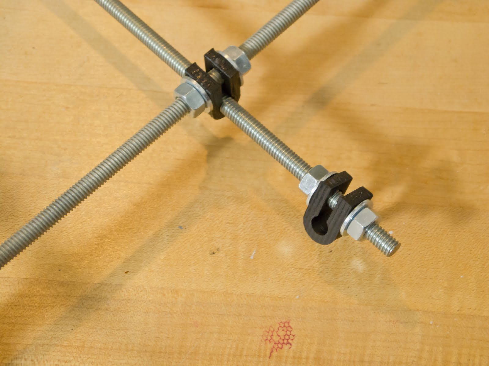
Before you get started we should make sure your printed plastic parts are cleaned up and ready to use. Like these bar clamps pictured above, they might need some work. Take a craft knife to clean up the stringy bits around the outside, and push drill bits of appropriate size through the holes by hand. Run the bit back and forth, twisting a little between stokes, to make sure you have the hole smooth all the way around. Cut apart any of the pieces that came stuck together due to being printed close together.

Triangles

The triangles of threaded rod make up the main structure for the frame.


The parts you'll need are three 370mm rods (14 5/8"), 14 washers, 14 nuts, bar clamp, three vertices (two footed and one top vertex) a 5/16" drill bit and hobby knife. You'll also need a ruler.


1.) Begin building by threading a bar clamp assembly on to the middle of a 370mm rod. A bar clamp assembly consists of a nut, washer, bar clamp, washer and nut, in that order. Do not tighten the nuts around the bar clamp. They should remain loose until we install the Y axis, later.


2.) Put a footed vertex assembly on both ends. This will form the base of the triangle for the frame. The vertices are positioned with the foot down, inserting the rod into the lower holes, in the narrow side. The vertex should face outward, curving away from the center of the rod. The vertex assembly is a nut, washer, footed vertex, washer, and nut, in that order. The outer-most nut should just fit on to the rod. Keep the assembly loose for now.


3.) Loosely assemble two more pieces of 370mm rod in the remaining holes on the narrow of the vertices. Be sure to follow the pattern of nut, washer, plastic, washer and nut. Throughout the construction, wherever there is a nut holding a plastic piece in pace, there is always a washer in between. Again, the outter-most nut should just barely fit on to the end of the rod, and nothing should be tightened down yet.


4.) At this point you should have a triangle shape missing the vertex at the top. Thread on a nut to the ends of each open rod, slide on washers then carefully insert the rods though the non-footed vertex, positioned so that the vertex forms a U shape. As always, if you have to use force to get something to fit you are doing something wrong and you need to stop and figure out what it is. The nuts and washers should start about an inch from the end, and then after you put on the vertex you can thread on the nuts further down until the rod just starts to peak out of the plastic. Do this on both sides and fit washers on to the rods. Threading both inside nuts a little further, you should be able to start both of the outer nuts. With both nuts started you can proceed to turn all the nuts until you have them all fully on to the rods at the end. Following this process is easier than threading them on individually, because things get kind of tight up there when you don't do them together.


4.) Hand tighten all the nuts on the vertices and you wind up with a sturdy structure. As you go around the triangle and tighten the nuts, measure the distance between the vertices. The vertices should be 290mm (11 13/32") apart, measuring from the inside edge of the plastic. Be sure the ruler does not ride up on the washer next to the printed piece. Try to make sure there is about the same amount of threaded rod coming out of the nut on each end of each rod as you adjust, measure and tighten.


5.) Repeat all these steps to build the second triangle.

Front Cross Supports

Next, assemble the front cross supports for the machine. This construction will link the two triangles together with two of the 294mm sections of threaded rod.

The parts needed for this step are two 294mm (11 5/8"), 17 nuts, 20 washers, two fender washers, two bar clamps, and the Y motor bracket printed part.

1.) Make the bottom front cross support by threading on the Y bracket assembly at it's lower junction on to a 294mm rod. The Y bracket has two 5/16" holes in it. There are two semi-circular sides, one with a larger radius than the other, and a side that is straight. The bottom junction is the 5/16" hole that is at the end of the straight section. The Y bracket will be oriented so that the straight section is parallel to the table, and the larger diameter semicircle faces inwards toward the machine. Thread on a nut, a washer, the Y bracket, then a washer and nut.

UPDATE: Proviso, caution, addendum alert! Measure the motor shaft length, or refer to the motor specifications (specs for the ones I got from Ultimachine, here.) If it's 25mm long, you're all good. If, like mine, the shaft is 20mm, leave out the two spacer washers between the nut to the right of the Y motor bracket and the left fender of the pulley. Details pending.


2.) The top front cross support looks complicated, but if you break it down it's really not so bad. Like the bottom cross support, the Y bracket on top has a nut with a washer against the plastic on either side. Right up against the Y bracket's right nut there is a pulley assembly (you kids in the back, stop giggling. Thank you.) Since there is already a nut for the Y bracket, you just need to put two washers on as as spacers. Then slide on a fender, a washer, a bearing, a washer, and a fender, held together with a nut. On either side of the Y bracket and pulley there is a bar clamp assembly that's just like the ones that went on the bottom of the triangle. The ends of the rods are finished with nut, washer, washer and nut combos.


Rear Cross Supports

Since the rear cross supports are not joined by a bracket as is the front, you just need to prepare them for final assembly of the frame.

The parts you need for this step are two 294mm rods (11 5/8"), 14 washers, 14 nuts, two fender washers, a bearing, and two bar clamps.

1.) The top cross rear support rod has a pulley assembly in the middle, but with a nut instead of the spacer washers. On either side of the the pulley add a bar clamp assembly. Finish the ends of the rod with a nut, washer, washer, nut combo.


2.) The bottom rear cross support rod is simply a nut, washer, washer, nut combo on each end.


Frame Assembly

The top cross supports are built in the process of constructing the frame.

The parts required for this step are two 440mm (17 5/16") rods, 12 nuts, 16 washers, and the previously assembled and prepared frame parts.

1.) Remove a nut and one washer each from one end of the front cross supports. Insert the ends of the rods through the holes of one vertex of a triangle. The top cross support should be oriented with the frame up so it is closer to the top vertex than the bottom cross support. Fasten the rods to the triangle with the washers and nuts. Leave loose.


2.) Repeat for the other end of the front cross supports. Do not tighten.

3.) Assemble the rear of the frame by positioning the top and bottom rear cross supports in the remaining footed vertices, using the washer and nut on the ends of each rod to attach them.


4.) Set the frame on it's feet and begin building the top of the frame by inserting a 440mm long threaded rod though one side of the top vertex of a triangle. Before inserting it into the opposite vertex, thread on a washer, two nuts and a washer, in that order. Now insert the threaded rod though the vertex opposite the first. Turn the nuts so that each holds a washer against the inside of the opposing top vertices about 234mm (9 7/32") apart, and so that even amounts of threaded rod protrude from the outside of each vertex. Fasten the rods loosely in place with washers and nuts.


5.) Repeat for a second top cross support rod.

6.) On to the protruding ends of the top cross support rods slide washers and then the Z motor mounts, then washers and then nuts. The well of the motor mounts should be facing up, like a cup.


Tighten the Frame

At this point the frame should be a little loose, but roughly in the correct shape.


1.) Make two jigs for precise measurement between vertices. The jigs may be made from any firm material. Wood dowels would probably be best, but I just used what I had on hand. I was afraid that the potential for and uneven end would introduce some variability so I cut away part of the ends with a skill saw.


2.) Make one jig to precisely 290mm (11 13/32") and label it "J1". It's really important to get the jigs to the exact length specified. My technique was to cut it a few millimeters too long and gradually file it down to length, frequently checking against a ruler.

3.) Make one jig to precisely 234mm (9 7/32") and label it "J2". Use either metric or SAE units, as they are approximately equivalent but not interchangeable.

4.) Use J1 to carefully adjust the distance between vertices of the triangles. Measure from the inside of the vertices. Tighten so that the nuts won't move, but be careful not to crack or crush the plastic.


5.) Use J2 to carefully adjust the distance along the cross supports between triangles. Measure from the inside of the plastic pieces. Tighten the nuts with a wrench but do not crush the plastic.

Bottom Cross Support

At this point the frame should be stable and precisely adjusted to size.

For this step the following parts are required: one 440mm (17 5/16") rod, two bar clamps, four nuts, and four washers.

1.) Insert the 440mm rod through the bar clamps under the frame. Note: the visual instructions I used indicate this rod should go on to the bar clamps above the bottom support rods. However, some people reported that this caused wear on the belt driving the print surface. Now it is recommended that this cross support be slung under the machine. I followed the new recommendation. Whether that will come back to bite me remains to be determined.


2.) On to each end of the bottom cross support rod assemble a bar clamp. The bar clamps should be finger tight and jut out from the rod in the same direction.

3.) Align the bottom rod. Construct a plumb line. I used yarn and a pair of nuts I'd used earlier when cutting the threaded rod. Suspend the plumb line from the notch a top motor mount with the weight just off the table enough for it to swing freely. The cross support will be aligned slightly off-center. The vertical holes formed by the bar clamp should align with the plumb line.


The frame is complete!

There is video of this entire process. I will update this post as finished video becomes available.